Part 5: Multi-Power an Arduino for G35 Lights
This is the fifth in a series of blog posts about researching and rewiring Christmas lights to work with Arduino devices.
In the last post I set up an Arduino to remote control a set of Home Collection xmas lights using RF codes. This post will be about the other set of lights, the GE Color Effects.
I was able to get these lights to work with an Arduino 2560, running the lights off the power provided by the Arduino board. This raised a question as to what current the lights would actually draw and how would the lights be affected by using the Arduino board instead of the wall wart.
The wall wart has a nice easy-to-read sticker that says it provides 5 Volt and 3 Amp output. A StackExchange question about Arduino Current suggests the lights are only receiving 400 mA. A few years ago Todd Harrison did a teardown of the 50-light G35 LED set and found that the lights maxed out at 1.75 Amps.
In my own test, I found the lights to appear a bit brighter when connected to the wall wart instead of the Arduino. I would prefer this setup and I planned out the connections.
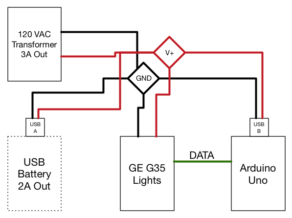
I split a USB-A to USB-B cable in two; USB-B powering the Arduino and USB-A to pull power from a USB battery. The positive lines from these USB cables were connected to the positive lines for the G35 lights and the cable to the transformer. A separate four-way connection was made for the ground wires.
This would give me the option to power the lights either through an outlet over 120 VAC, or through a USB battery to make the lights portable. I don’t know what would happen if both the transformer and the USB battery were connected, and I don’t intend to test it without doing more research. (Although I can’t think of a reason to run both.)
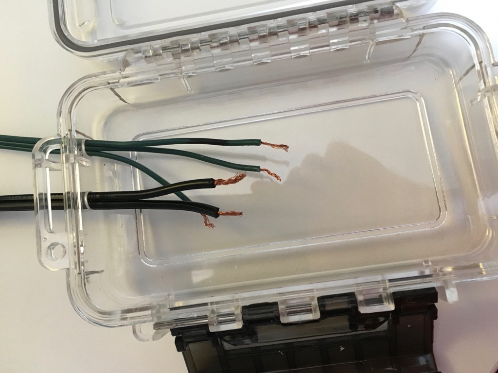
I drilled two holes in the weatherproof case for the transformer wires and G35 wires to ingress.
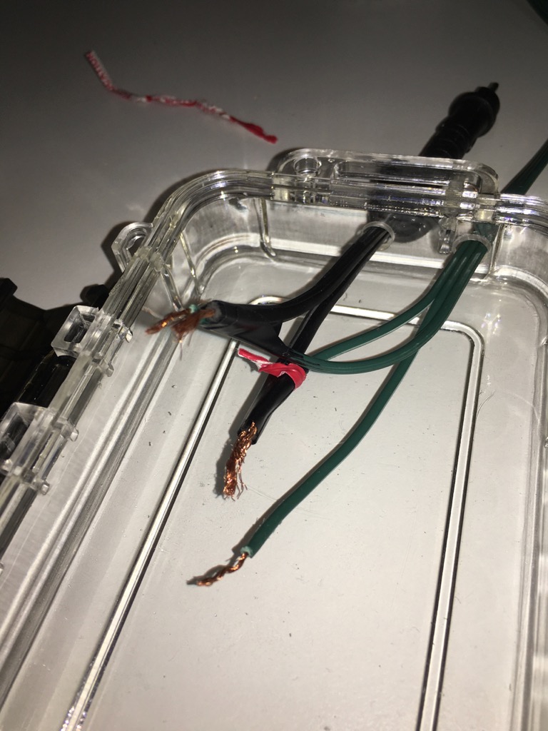 
Next the wires were taped together.

Next the wires were taped together.
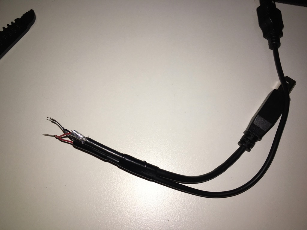
Then I connected the USB cables, using electrical tape to keep the wires from separating.
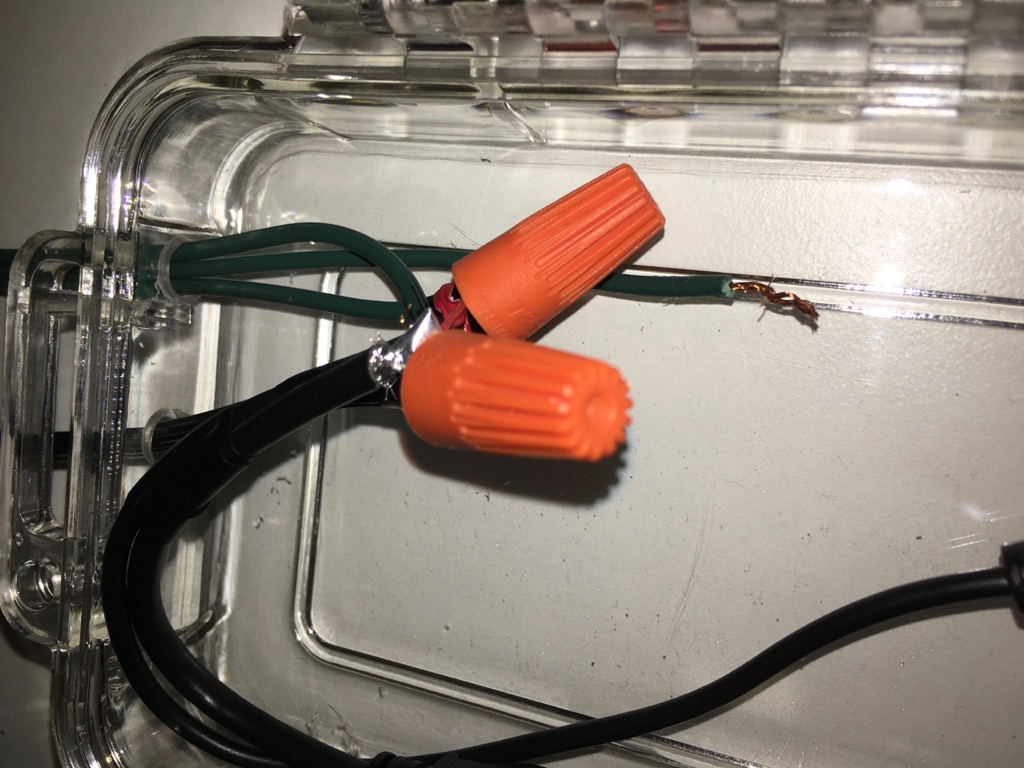
Then I connected the USB wires with the lights and transformer wires, using wire connectors to secure them.

Connecting the transformer wire to the transformer brick, the data line to the Arduino, and the USB-B to the Arduino, the lights came to life!
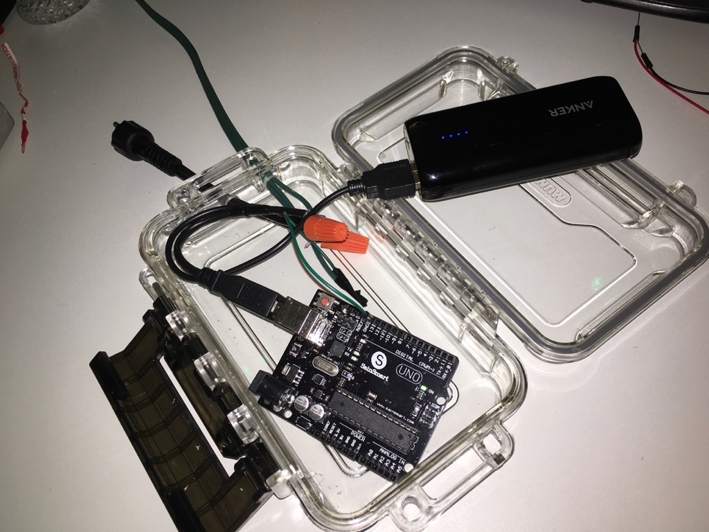
Turning off the power and disconnecting the transformer wire, then connecting the USB-A to a USB battery works as well.
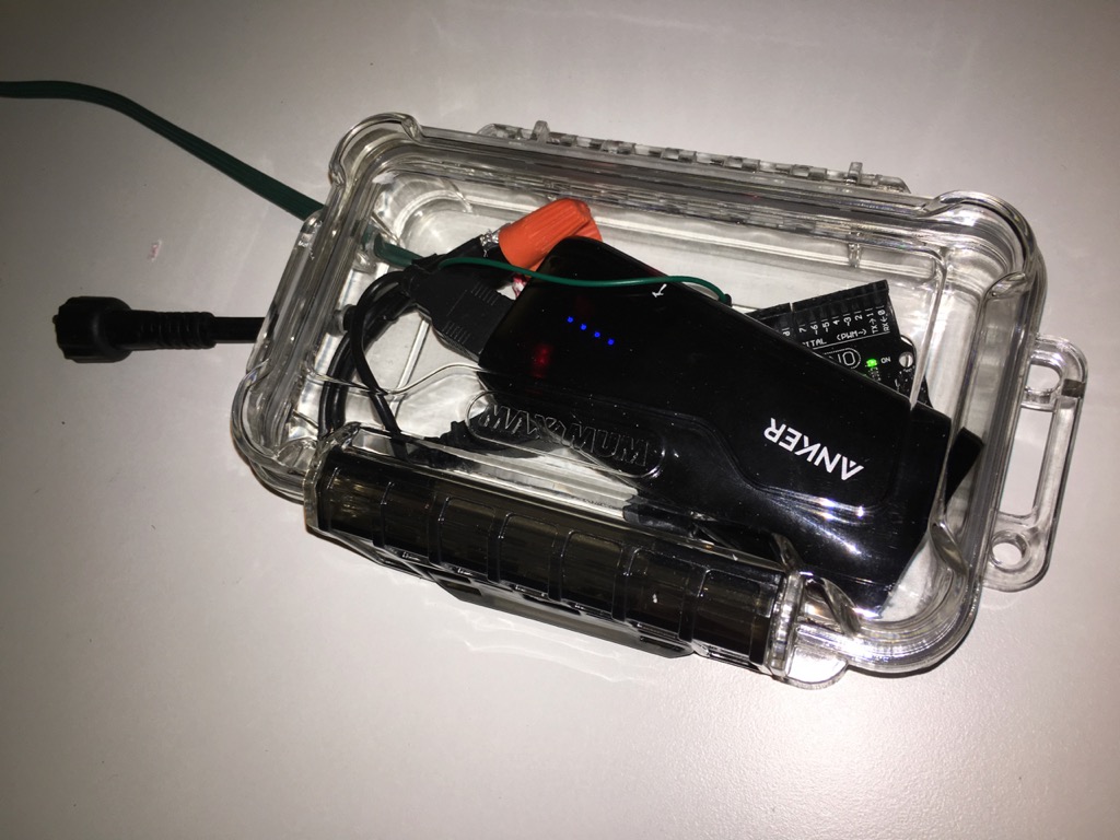
And just to be sure, the case DOES close.
I’m pretty pleased with the case, although I need to seal the holes where the wires enter with hot glue or similar. It mainly needs to provide support and keep out snow and should be safe to leave out to -35 Celsius without failing.
Open controller box, disconnect wires to original controllerWire power brick to Arduino board, make sure the 5V worksWire power and data lines from lights to Arduino board, test connection- Write Arduino code to do more advanced light programs
- Connect Arduino to WiFi or Bluetooth and setup remote control from iOS or from a Raspberry Pi
Find a weatherproof housing for the ArduinoFind weatherproof cables to extend the connections from the Arduino controller to the lights and to the power brick- Test outside!
I have an ESP8266 module that I could use to provide either a TCP or MQTT type server for communicating with the Arduino. I will try setting that up and control the Arduino remotely through a web page next time.